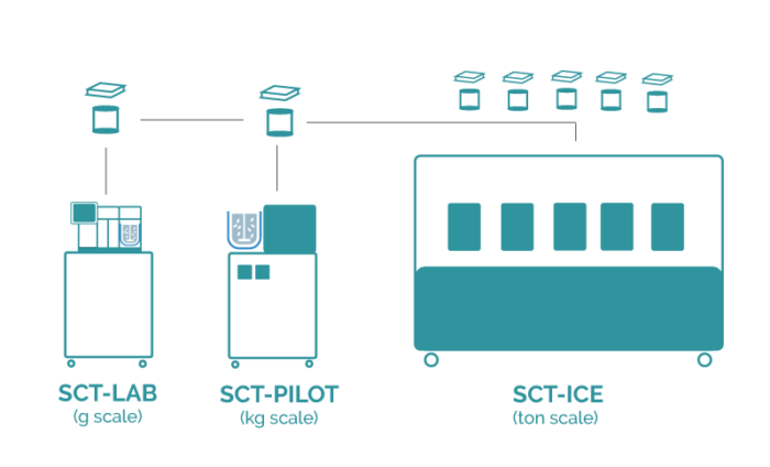
Upscaling the crystallization technology from lab to production scale
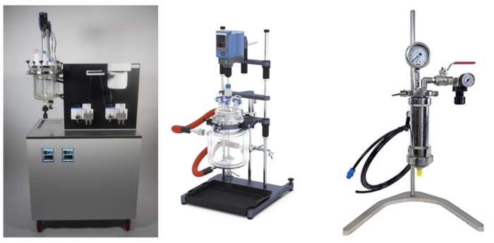
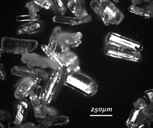
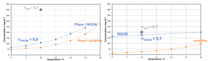
As the parameter settings at lab scale are completely identical to pilot scale productions, one just has to connect a second, third, fourth, or more reactors with its own flow control to generate a productive environment that produces sufficient crystalline material per hour of operation. For example, there is no work-up necessary for the upscaling towards kg productions for lactose. Even more, productions have been performed using two reactors in parallel with the same execution, on 12 liter of solution, with the same setup as mentioned in the previous blog. After filtration and drying the material attributes are exactly in line with previous findings.
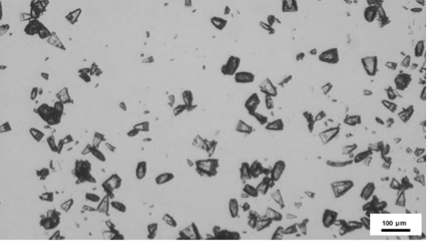
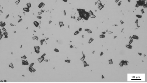
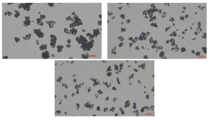
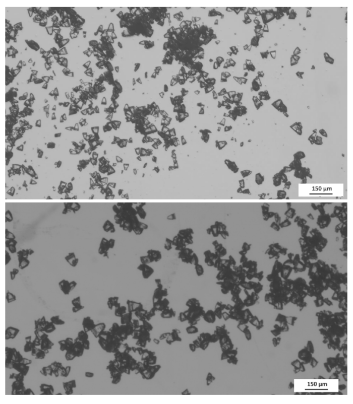
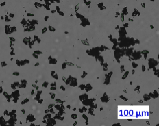
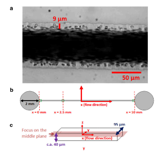
Figure 1: Microscopic images of a Lactose production using two parallel reactors operating at the same time.
|
Characteristics
|
|
|---|---|
|
Average
|
54 µm
|
|
Standard Deviation
|
16 µm
|
|
D50
|
52 µm
|
|
0,71
|
|
Table 1: Material attributes of a Lactose Production using 2 parallel reactors.
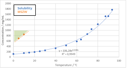
Lactose is due to its high solubility in water, 150 mg/mL at 5°C an exceptional molecule as the theoretical yield one can obtain is bu 82% for any crystallization process not using antisolvents to pump out any remaining solute in solution. With this in mind, the process itself has a very respectable 95% mass yield. At this production scale, knowing that there are relatively large losses in the growth tank, transfer lines, etc. This is a good value for any process. Lactose comes as a very pure product ad requires only water as solvent so direct recycling of filtered product is absolutely a possibility. The following production design is therefore proposed:
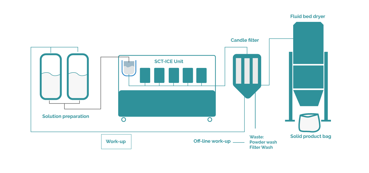
Figure 2: Process Design for the continuous crystallization of Lactose
Batch size determination, production strategy and the resulting construction decide then on the total reactors present on the machine. For Secoya, these reactors are regarded as single-use reactors during one single batch production with no events occurring. The cleanability of these reactors, especially when PFA polymer is chosen as reactor material is considered to be insufficient. For other reactor materials like Stainless Steel a full Clean in Place (CIP) strategy can be put in place.
The production strategy in a company depends then on the annual requested volume and prospection. In this example 100 tonnes of dry product is required per year. The particular client demands batch productions split per week, in three shifts, full arrest over the weekend. A maximum of 40 production weeks is foreseen, the batch size is defined by what is weekly produced, hence 40 batches will be produced per week. One such a production consists of 3 days of passage through the Secoya’s crystallization reactors, followed by a crystal growth cycle inside a waiting tank at 5°C, after which a fully sied candle filter and fluid bed dryer setup finish the product to its dry state.
Now, with a cautious estimation of a full yield – holding recycling into account – of 92 mass%, each production reactor produces 0.75 kg/hr at current set conditions – holding the density of the solution into account. Therefore a total of 47 reactors in parallel are capable of producing sufficient amount of material. Secoya limits to 50 of these reactors in parallel as otherwise the control and monitoring of flow rate and temperature could be at risk, however we are inside this limit for this specific application. The client would use 3 crystal growth tanks for completion. We have demonstrated that the addition of one or more production lines to the growth tank is independent of the final result. This is clearly due to the fact that there is no secondary nucleation occurring once the product exits our reactor: the crystals that have nucleated inside the reactor are simply grown to their equilibrium state.
|
Production parameters
|
|
|---|---|
|
Solution concentration
|
850 mg/mL
|
|
Total process yield with recycling
|
92 %
|
|
Flow rate per reactor
|
20 mL/min
|
|
12,5 g/min
|
|
|
Weeks of production
|
|
|
Production hours per week for simulation
|
|
|
Number of reactor required
|
|
|
Batch size dry powder
|
|
|
Treated liquid
|
|
Table 2: Production parameters at production scale
Conclusion
In conclusion, API crystallization presents multifaceted challenges, including controlling particle size and shape, managing polymorphism, and ensuring purity. Secoya Technologies addresses these complexities by offering versatile equipment capable of handling multiple crystallization modes and a range of particle sizes. Our solutions facilitate the development of complete process cycles from lab to pilot scale and beyond, enabling the direct achievement of optimal crystal sizes for solutes in solution. By leveraging our expertise and advanced technologies, we empower pharmaceutical manufacturers to overcome crystallization challenges, ensuring consistent quality and efficiency in API production.